
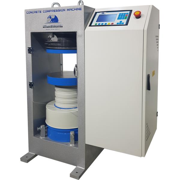
Automatic Concrete Compression Testing Machine, Welded Wall, Touch Screen
The Automatic range of 1500 kN, 2000 kN and 3000 kN Capacity Compression Testing Machines have been designed for reliable and consistent testing of a wide range of specimens. Machines confirm all EN, ASTM and BS standards written above. These also meet the requirements of CE norms for the safety and health of the operator.
Testing machines are supplied with EN compression platens as standard. Machines also comply with the ASTM C39 standard when used together with suitable platens.
The Automatic Compression Testing Machines allow inexperienced operators to perform the tests. Once the machine has been switched on and the specimen is positioned and centered by the help of centering apparatus. The only required operations are;
- Setting test parameters, including pace rate (only required when the specimen type is changed).
- Pressing the START button on the control unit
- The machine automatically starts the rapid approach, when the specimen touches the upper platen the rapid approach is ended and starts loading at the pace rate that selected by user and stops once the specimen fails.
- Automatically saves the test parameters and test results.
The Automatic Concrete Compression Testing Machines consist of;
Load Frame,
Automatic Hydraulic Power Pack,
Digital data acquisition & control system,
Distance Pieces, 30 mm, 50 mm and 80 mm,
Upper Platen (with ball seating assembly),
Lower Platen,
Loading Cylinder Assembly & Limit Switch for safety,
Front and Rear Protective Doors for safety,
Software and Ethernet Cable.
Concrete Compression Load Frame
Capacities of 1500 kN, 2000 kN and 3000 kN Load Frames are most popular and available models for welded type frames.
The load frame provides the stability needed for accurate and repeatable test results over the years of operation.
The frames are supplied with factory calibration certificate for force transfer stability and the self-alignment of the upper loading platen conforming to EN 12390-4.
Upper Platens/Lower Platens
The platens enable the testing of a wide variety of cylinder, cube blocks or similar samples.
• Manufactured from high quality steel, which is then hardened, smoothed and finished.
• The roughness value for the surface texture of the auxiliary platens is ≤ 3.2 µm.
• Ø 165 mm and Ø 300 mm Upper Platen (with ball seating assembly) and Lower Platen have centering rings on the lower platens for proper centering of 100 mm and 150 mm cube, 100 mm and 150 mm cylinder samples.
Block Platens with Sliding Rail Assembly
STANDARDS: EN 772-1, 12390-4
Block Platens with Sliding Rail Assembly are installed on the compression testing machines for testing concrete blocks and other structural materials. The Sliding Rail Assembly allows the platens to be easily installed without removing the existing Ø 300 mm compression platens. This assembly should be factory installed.
It should be noted that after installing, the vertical clearance between the platens decreases by 50 mm.
Block Platens Lifting Assembly is used for easy removal of the lower platen of Block Platens and easy replacement of the distance pieces between the piston and the lower platen.
Distance Pieces
Distance pieces are used to reduce the amount of vertical clearance between the upper platen and the lower platen.
Loading Cylinder Assembly & Limit Switch
All frames have a single acting up stroking ram. The diameter of piston changes with regard to the capacity.
The maximum ram stroke is 50 mm, a limit switch is fitted to prevent over travel of the ram which cuts the power to the pump for safety.
At the end of the test process to start a new test the piston returns to default position.
The pressure transducer is used for load measurements.
There is a low friction coaxial PTFE seal between the cylinder and the piston fitted to the cylinder.
HYDRAULIC POWER PACK AND H-TOUCH PRO MAX CONTROL UNIT
Hydraulic Power Pack
Automatic Hydraulic Power Pack, dual stage, controlled by H-Touch Pro Max Control Unit is designed to supply the required oil to the load frames for loading.
Controller unit has a simple and compact configuration. The Hydraulic Power Pack, Control and Read out Units are positioned on the right-hand side of the load frame for easier accessibility, increased productivity and for safer operations.
Very silent power pack can load the specimen between 1 kN/sec. to 20 kN/sec, with an accuracy of ±5%. A Rapid approach pump is supplied as standard. Safety valve (maximum pressure valve) is used to avoid machine overloading.
Maximum working pressure of the system is 400 bar.
Dual Stage Pump
The dual stage pump is formed by two groups;
1.Low pressure gear pump
2.High pressure radial piston pump
On the dual stage pump, a high delivery, low pressure gear pump is used for rapid approach, while a low delivery, high pressure radial piston pump is used for test execution. The rapid approach facility shortens the time interval from piston start until the upper platen touches to the specimen. This excellent feature helps to save a lot of time when a large number of specimens are going to be tested.
Motor
The motor which drives the dual pumps in an AC motor and it is controlled by motor inverter. The variation in the oil flow is executed with the variation of the rotation speed of the motor.
Distribution Block
A distribution block is used to control the oil flow direction supplied by the dual stage pump, the following parts are fitted to the distribution block; Solenoid valve, Safety valve (max. pressure valve), Transducer, Low pressure gear pump and High pressure radial piston pump.
High Precision Pressure Transducer
The range of Automatic Machines can be upgraded with option High Precision Pressure Transducer special calibration Class 1 starting from 1% of the full range.
This unique performance enables the machines to be used for a considerable number of applications including:
• Early age(2 or 3 days) compression strength tests
• Flexural and splitting tests by using proper accessories
• Mortar (Cement) compression tests by using proper accessories
• Core Testing
Oil Tank
The tank includes enough oil to fill the mechanism which pushes the ram during the test. The level and oil temperature can be seen on the indicator fitted to the tank. It has 25 L capacity. Hydraulic motor oil, number 46, must be used.
Digital Data Acquisition & Control System
All the operations of H-Touch Pro Max Control Unit are controlled from the front panel color resistive of TFT-LCD Touchscreen display and function keys.
The unit has easy to use menu options.
It displays all menu option listings simultaneously, allowing the operator to access the required option in a seamless manner to activate the option or enter a numeric value to set the test parameters.
H-Touch PRO Max Control Unit enable simultaneously display machine status, test values, warnings during operation and test graphs such as load-time or load-displacement curves in real time.
Digital graphic display of the unit is able to draw real-time "Load vs. Time" or "Stress vs. Time" graphics.
Main Features of H-Touch Pro Max Control Unit
- 2 analog channels for load cell or pressure sensors or displacement sensors.
- Can control 2 frames
- Provides load control of two separate testing frames with Closed-loop PID.
- Optionally supplied-integrated thermal printer (If requested, must be specified in the order)
- Real-
Product Overview
The Automatic range of 1500 kN, 2000 kN and 3000 kN Capacity Compression Testing Machines have been designed for reliable and consistent testing of a wide range of specimens. Machines confirm all EN, ASTM and BS standards written above. These also meet the requirements of CE norms for the safety and health of the operator.
Testing machines are supplied with EN compression platens as standard. Machines also comply with the ASTM C39 standard when used together with suitable platens.
The Automatic Compression Testing Machines allow inexperienced operators to perform the tests. Once the machine has been switched on and the specimen is positioned and centered by the help of centering apparatus. The only required operations are;
- Setting test parameters, including pace rate (only required when the specimen type is changed).
- Pressing the START button on the control unit
- The machine automatically starts the rapid approach, when the specimen touches the upper platen the rapid approach is ended and starts loading at the pace rate that selected by user and stops once the specimen fails.
- Automatically saves the test parameters and test results.
The Automatic Concrete Compression Testing Machines consist of;
Load Frame,
Automatic Hydraulic Power Pack,
Digital data acquisition & control system,
Distance Pieces, 30 mm, 50 mm and 80 mm,
Upper Platen (with ball seating assembly),
Lower Platen,
Loading Cylinder Assembly & Limit Switch for safety,
Front and Rear Protective Doors for safety,
Software and Ethernet Cable.
Concrete Compression Load Frame
Capacities of 1500 kN, 2000 kN and 3000 kN Load Frames are most popular and available models for welded type frames.
The load frame provides the stability needed for accurate and repeatable test results over the years of operation.
The frames are supplied with factory calibration certificate for force transfer stability and the self-alignment of the upper loading platen conforming to EN 12390-4.
Upper Platens/Lower Platens
The platens enable the testing of a wide variety of cylinder, cube blocks or similar samples.
• Manufactured from high quality steel, which is then hardened, smoothed and finished.
• The roughness value for the surface texture of the auxiliary platens is ≤ 3.2 µm.
• Ø 165 mm and Ø 300 mm Upper Platen (with ball seating assembly) and Lower Platen have centering rings on the lower platens for proper centering of 100 mm and 150 mm cube, 100 mm and 150 mm cylinder samples.
Block Platens with Sliding Rail Assembly
STANDARDS: EN 772-1, 12390-4
Block Platens with Sliding Rail Assembly are installed on the compression testing machines for testing concrete blocks and other structural materials. The Sliding Rail Assembly allows the platens to be easily installed without removing the existing Ø 300 mm compression platens. This assembly should be factory installed.
It should be noted that after installing, the vertical clearance between the platens decreases by 50 mm.
Block Platens Lifting Assembly is used for easy removal of the lower platen of Block Platens and easy replacement of the distance pieces between the piston and the lower platen.
Distance Pieces
Distance pieces are used to reduce the amount of vertical clearance between the upper platen and the lower platen.
Loading Cylinder Assembly & Limit Switch
All frames have a single acting up stroking ram. The diameter of piston changes with regard to the capacity.
The maximum ram stroke is 50 mm, a limit switch is fitted to prevent over travel of the ram which cuts the power to the pump for safety.
At the end of the test process to start a new test the piston returns to default position.
The pressure transducer is used for load measurements.
There is a low friction coaxial PTFE seal between the cylinder and the piston fitted to the cylinder.
HYDRAULIC POWER PACK AND H-TOUCH PRO MAX CONTROL UNIT
Hydraulic Power Pack
Automatic Hydraulic Power Pack, dual stage, controlled by H-Touch Pro Max Control Unit is designed to supply the required oil to the load frames for loading.
Controller unit has a simple and compact configuration. The Hydraulic Power Pack, Control and Read out Units are positioned on the right-hand side of the load frame for easier accessibility, increased productivity and for safer operations.
Very silent power pack can load the specimen between 1 kN/sec. to 20 kN/sec, with an accuracy of ±5%. A Rapid approach pump is supplied as standard. Safety valve (maximum pressure valve) is used to avoid machine overloading.
Maximum working pressure of the system is 400 bar.
Dual Stage Pump
The dual stage pump is formed by two groups;
1.Low pressure gear pump
2.High pressure radial piston pump
On the dual stage pump, a high delivery, low pressure gear pump is used for rapid approach, while a low delivery, high pressure radial piston pump is used for test execution. The rapid approach facility shortens the time interval from piston start until the upper platen touches to the specimen. This excellent feature helps to save a lot of time when a large number of specimens are going to be tested.
Motor
The motor which drives the dual pumps in an AC motor and it is controlled by motor inverter. The variation in the oil flow is executed with the variation of the rotation speed of the motor.
Distribution Block
A distribution block is used to control the oil flow direction supplied by the dual stage pump, the following parts are fitted to the distribution block; Solenoid valve, Safety valve (max. pressure valve), Transducer, Low pressure gear pump and High pressure radial piston pump.
High Precision Pressure Transducer
The range of Automatic Machines can be upgraded with option High Precision Pressure Transducer special calibration Class 1 starting from 1% of the full range.
This unique performance enables the machines to be used for a considerable number of applications including:
• Early age(2 or 3 days) compression strength tests
• Flexural and splitting tests by using proper accessories
• Mortar (Cement) compression tests by using proper accessories
• Core Testing
Oil Tank
The tank includes enough oil to fill the mechanism which pushes the ram during the test. The level and oil temperature can be seen on the indicator fitted to the tank. It has 25 L capacity. Hydraulic motor oil, number 46, must be used.
Digital Data Acquisition & Control System
All the operations of H-Touch Pro Max Control Unit are controlled from the front panel color resistive of TFT-LCD Touchscreen display and function keys.
The unit has easy to use menu options.
It displays all menu option listings simultaneously, allowing the operator to access the required option in a seamless manner to activate the option or enter a numeric value to set the test parameters.
H-Touch PRO Max Control Unit enable simultaneously display machine status, test values, warnings during operation and test graphs such as load-time or load-displacement curves in real time.
Digital graphic display of the unit is able to draw real-time "Load vs. Time" or "Stress vs. Time" graphics.
Main Features of H-Touch Pro Max Control Unit
- 2 analog channels for load cell or pressure sensors or displacement sensors.
- Can control 2 frames
- Provides load control of two separate testing frames with Closed-loop PID.
- Optionally supplied-integrated thermal printer (If requested, must be specified in the order)
- Real-